

Posted on: April 8, 2026 | Category: Electrical Engineering | Tags: three-phase electric motor, motor structure, stator, rotor, industrial motors
Many people are unfamiliar with electric motors, having never touched or seen one. However, electric motor technology is applied in every aspect of our lives and work. For example, on a small scale, the electric toothbrush, hair dryer, and electric fan we use to brush our teeth in the morning are driven by electric motors; on a larger scale, the subway we ride to work every day, elevators, water pumps for building water supply, cranes on construction sites, electric cars, and so on are all driven by electric motors. It can be said that wherever electric motor technology brings convenience and efficiency to our lives and production, electric motor technology is used. Since electric motor technology is so important, today we will learn about the three-phase electric motor, which is frequently used in engineering.
An Overview of Three-Phase Electric Motors
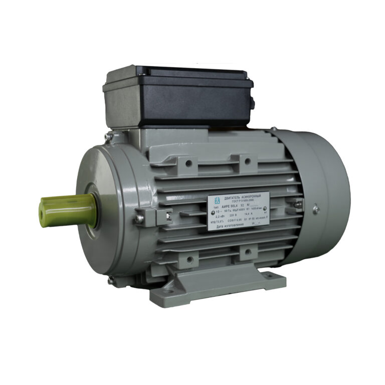
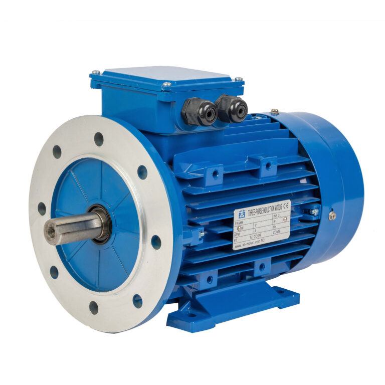
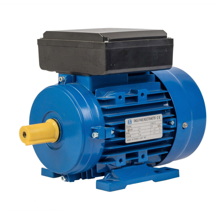
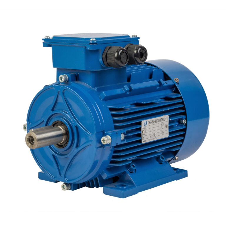
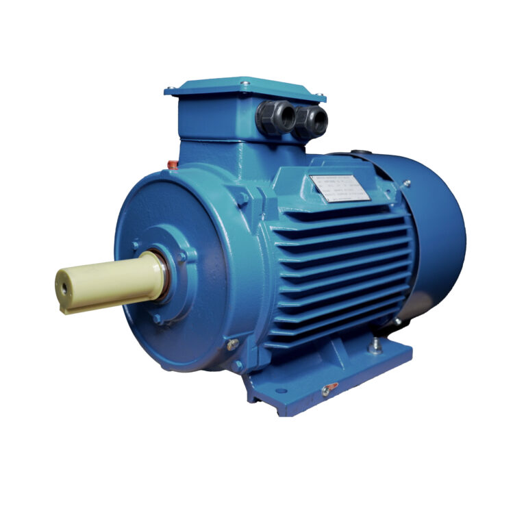
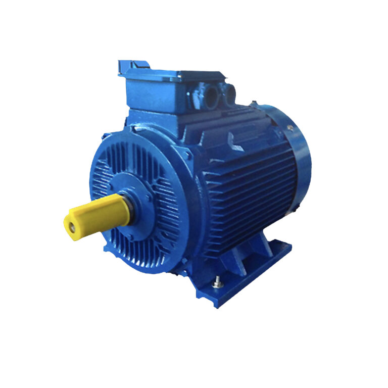
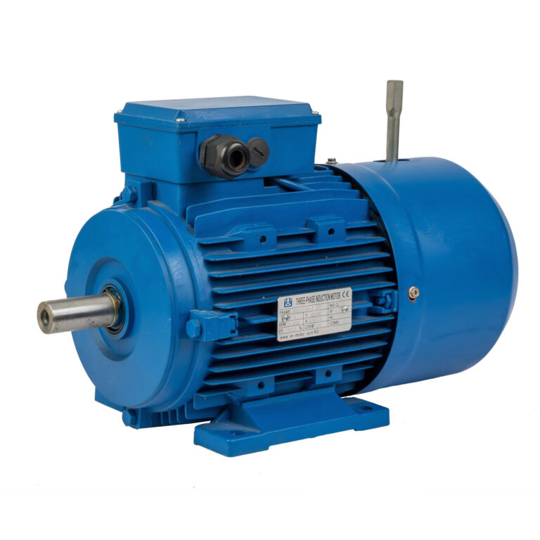
From the outside, a three-phase electric motor appears to be just a simple metal casing, but internally it is a precisely designed system: every component works together to convert electrical energy into mechanical energy with extremely high efficiency. The structure of a three-phase electric motor is actually quite simple, mainly consisting of three parts: the stator, the rotor, and the casing. Depending on the rotor construction, it is divided into two types of three-phase asynchronous motors: squirrel-cage and wound-rotor.
The squirrel-cage rotor winding is made in a squirrel-cage shape, with copper or aluminum bars placed in the slots of the rotor core, connected at both ends by end rings. The rotor winding of a wound-rotor three-phase asynchronous motor is a three-phase winding, which can be connected in a Y or Δ configuration. The three leads of the rotor winding are connected to three slip rings respectively, and are led out by a set of brushes. This allows a stationary external circuit to be connected in series to the rotor winding circuit, the purpose of which is to improve the characteristics of the motor or to regulate the speed.
Key Component 1: The Stator
Stator Core: The Backbone of the Magnetic Circuit
The stator core is the foundation of the motor’s magnetic circuit, constructed from ultra-thin insulated silicon steel sheets of 0.35~0.5mm thickness. This choice is not arbitrary but rather a deliberate one to minimize eddy current losses and reduce waste. Why choose insulated silicon steel sheets? Because silicon steel has excellent magnetic permeability and low magnetic reluctance, allowing the magnetic field to pass smoothly; while inter-sheet insulation prevents current from circulating inside the core, reducing ineffective heating and thus improving efficiency.
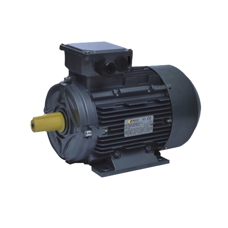
Dayou Motors’ entire series (ME2, ME3, YE2, YE3) uses high-quality cold-rolled silicon steel sheets, whose magnetic properties are significantly stronger than hot-rolled silicon steel. The silicon steel sheets are formed by high-speed stamping, with evenly distributed slots on the inner side to embed the stator for winding. Furthermore, the slot design can be professionally customized according to the motor’s power and application.
Our small and medium-sized high-efficiency motors (such as the ME2 aluminum alloy motor) use semi-closed slots, effectively reducing leakage flux and improving efficiency and power factor; high-power industrial motors use semi-open slots, facilitating winding and insulation. Each stator core undergoes high-precision lamination to ensure tightness, uniformity, gaplessness, and misalignment. Even minute defects can disrupt the uniformity of the magnetic field, affecting motor performance.
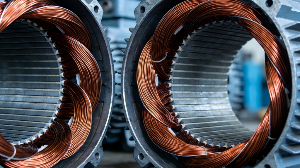
Stator Windings: The Motor’s Circuit System
If the stator core is the magnetic circuit skeleton, then the stator windings are the motor’s circuitry: three-phase alternating current is input through them, generating a rotating magnetic field. The windings typically use high-grade insulated copper or aluminum wire: copper wire is more efficient and has a longer lifespan; aluminum wire offers a cost advantage in certain applications.
The windings consist of three independent coils, evenly distributed within the core slots with a 120° electrical angle difference. This 120° distribution structure gives three-phase motors a natural high efficiency: when three-phase alternating current is applied, the currents in the three windings alternate sequentially, creating a uniformly rotating magnetic field. Unlike single-phase motors, it does not require starting the windings or a commutator. Dayou Technology uses a combination of fully automatic and semi-automatic winding equipment, effectively improving winding precision, which is one of the core advantages of our advanced production lines.
Key Component 2: The Rotor
The rotor is the rotating power-generating component of an electric motor. It rotates under the influence of the stator’s magnetic field, converting magnetic force into mechanical torque. A very small air gap exists between the stator and rotor, which is one of the most critical design parameters of an electric motor. An excessively large air gap reduces efficiency and power factor; an excessively small gap can lead to friction or even rotor rubbing. Dayou Motors uses micron-level machining precision to ensure a uniform air gap throughout the circumference, resulting in less vibration and higher efficiency.
Rotor Core: Matching the Stator Magnetic Circuit
The rotor consists of a rotor core and rotor windings. Most industrial three-phase motors use squirrel-cage rotors due to their simpler and more reliable structure. The rotor core is also made of 0.35~0.5mm thick insulated silicon steel sheets, matching the stator’s magnetic circuit, but its slots are on the outer side. The rotor core is tightly fixed to the shaft. Like the stator, it uses the same grade of silicon steel to ensure magnetic circuit coordination, reducing losses and improving overall efficiency.
To enhance structural robustness, the core of small and medium-power motors can be directly heat-fitted onto the shaft; for ease of assembly and maintenance, high-power motors generally use a support structure.
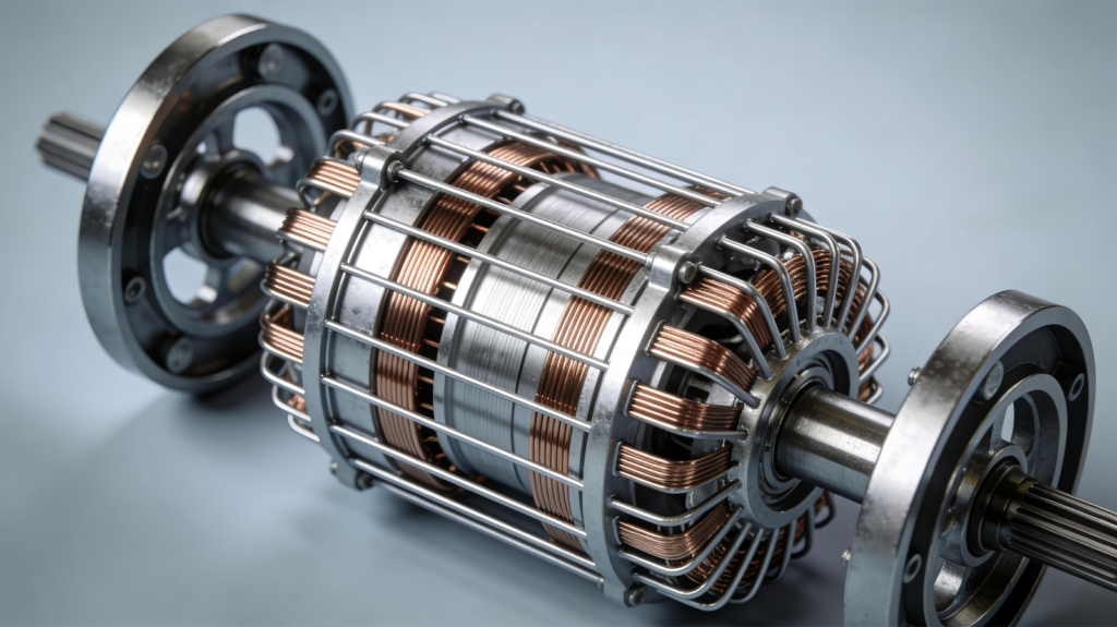
Rotor Windings: Types and Functions
The squirrel-cage winding consists of slotted conductors and short-circuited end rings forming a closed loop. Our IE3 high-efficiency motor uses copper conductors, which have lower resistance, generate less heat, and are more efficient; our standard series uses cast aluminum rotors, offering better cost-effectiveness. The induced current generated by the stator rotating magnetic field cutting the conductors can drive them to produce electromagnetic torque, which in turn drives the rotor to rotate. Its speed is slightly lower than the magnetic field speed; this phenomenon is called slip, hence the name asynchronous motor.
Wound-rotor motors are suitable for high starting torque and speed-regulating applications, but require maintenance. DaYou Technology can also customize wound-rotor motors according to specific equipment requirements.
Auxiliary Components: Ensuring Safe and Durable Operation
A complete electric motor relies on numerous auxiliary components to ensure safe and durable operation. These components are often overlooked, but they directly impact the motor’s lifespan, reliability, and operational stability. Dayou Technology never compromises on auxiliary components; we use high-quality parts of the same grade as the stator and rotor.
- End Cover & Bearings: The end cover supports the rotor shaft via bearings, whose function is to minimize friction. We use high-precision deep groove ball bearings or roller bearings, coupled with long-lasting grease. The dustproof and waterproof performance of the sealed bearing cover allows for lifetime maintenance-free operation in most scenarios. High-precision machining ensures accurate rotor alignment and uniform air gap, reducing vibration and noise at the source.
- Cooling System: Core losses, winding losses, and friction encountered during motor operation can generate heat. The cooling fan mounted on the shaft rotates synchronously with the rotor, generating forced airflow over the cooling fins for rapid heat dissipation. Our fan blades are aerodynamically optimized, offering high airflow and low noise. The fan shroud protects the fan blades while guiding airflow for effective heat dissipation, making it particularly suitable for continuously operating equipment.
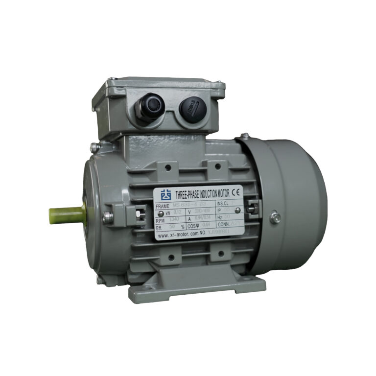
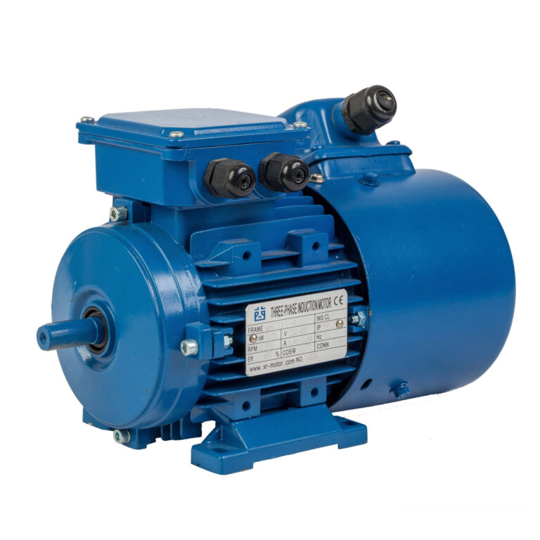
- Junction Box & Shaft: The junction box provides a safe power connection for machine operation, achieving IP55 protection. Meanwhile, DaYou Technology’s shafts are made of high-strength steel, precision-machined, and feature keyways for load connection. We offer a full range of mounting options, including B3, B5, and B14, to adapt to all industrial equipment. All mounting surfaces are precision-machined to effectively reduce vibration and extend service life.
Dayou Technology: Your Trusted Partner for High-Quality Three-Phase Motors
With 20 years of focus, DaYou Technology comprehensively optimizes its efficiency, reliability, and customization capabilities from a structural perspective. We precisely match materials according to energy efficiency ratings, employ automated production to ensure consistency, support flexible customization without adding extra cost, and implement stringent quality control on all components. We believe that by manufacturing stable, low-noise, long-life, and high-efficiency motors, DaYou Technology is increasingly gaining a prominent advantage in the global market.