


- Home
- Product
- GOST standard motor
- IEC standard motor
 MC Series single phase capacitor start asynchronous motor
- MY MYT series single phase capacitor running asynchronous motor
- ML Series single phase dual-capacitor asynchronous motor
- ME2 series three phase high efficiency aluminum housing motor(IE2)
- ME3 series three phase high efficiency aluminum housing motor(IE3)
- MS series three-phase aluminum housing motor (IE1)
- Y2 series three phase cast iron motor (IE1)
- YE2 series three phase high efficiency cast iron motor (IE2)
- YE3 series three phase high efficiency cast iron motor (IE3)
- Special application motor
- Rolling door motor
- Industry application
- News
- About us
- Contact us
- Certifications
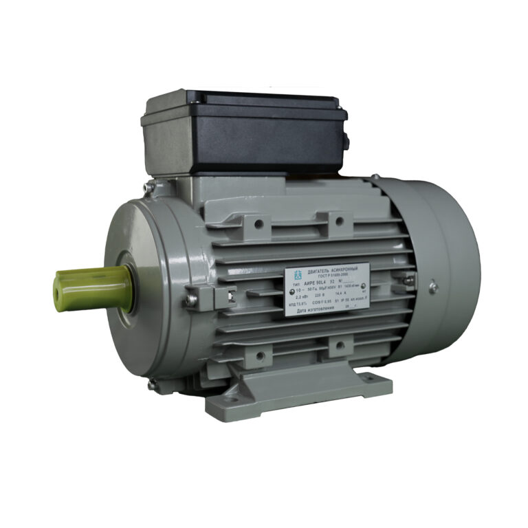
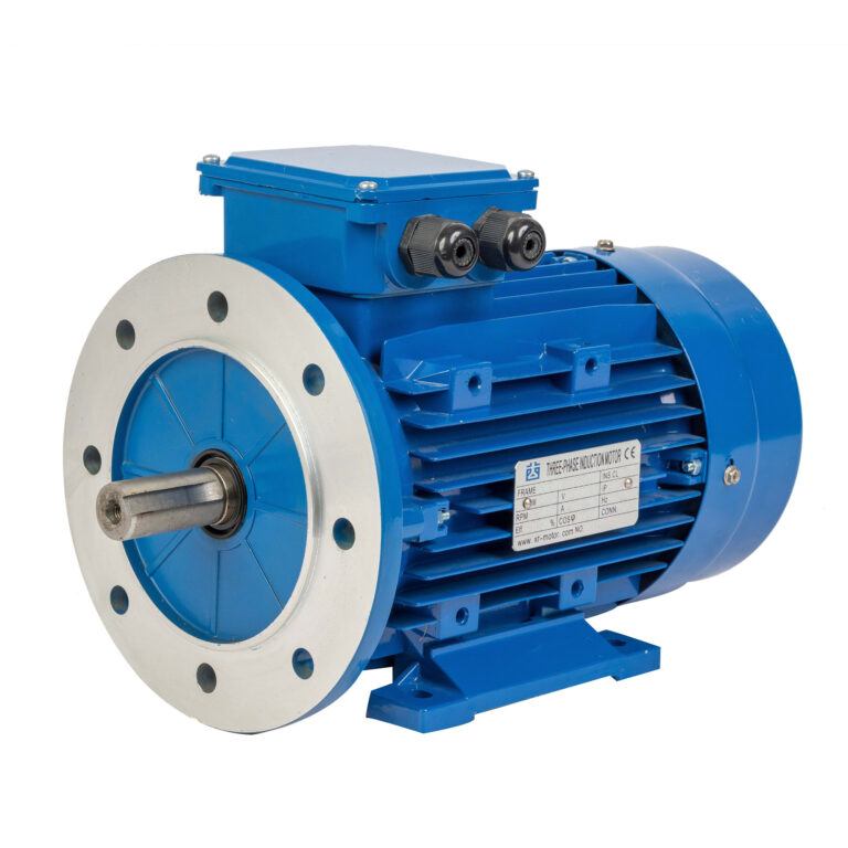
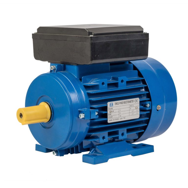
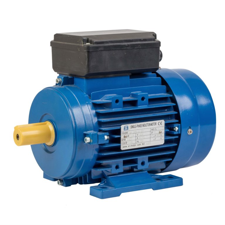
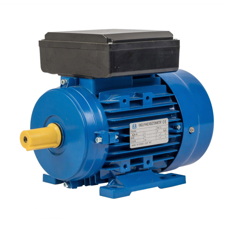
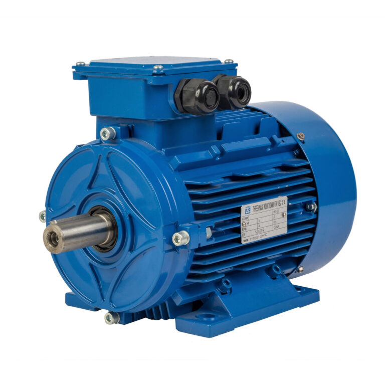
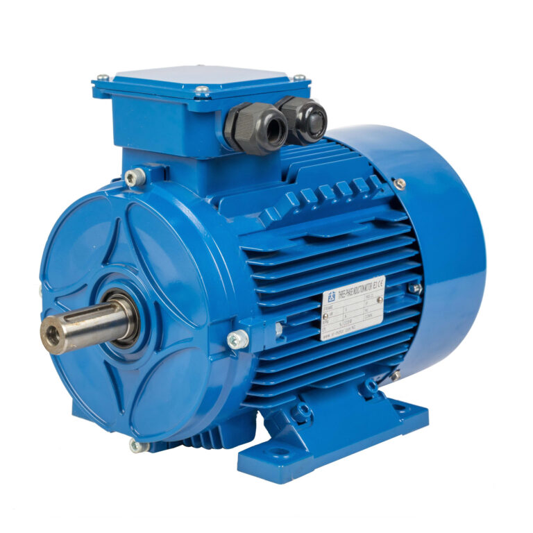
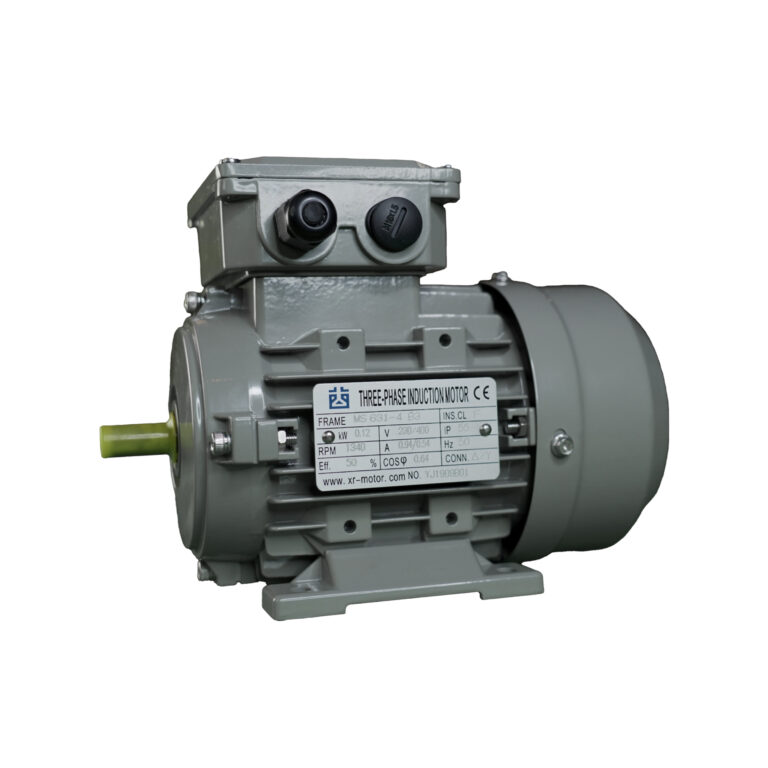
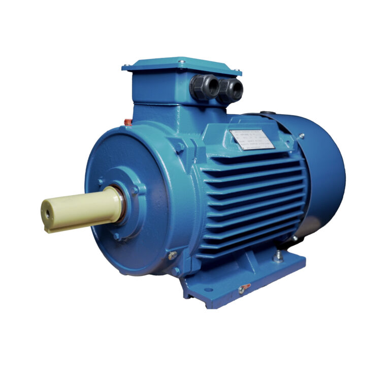
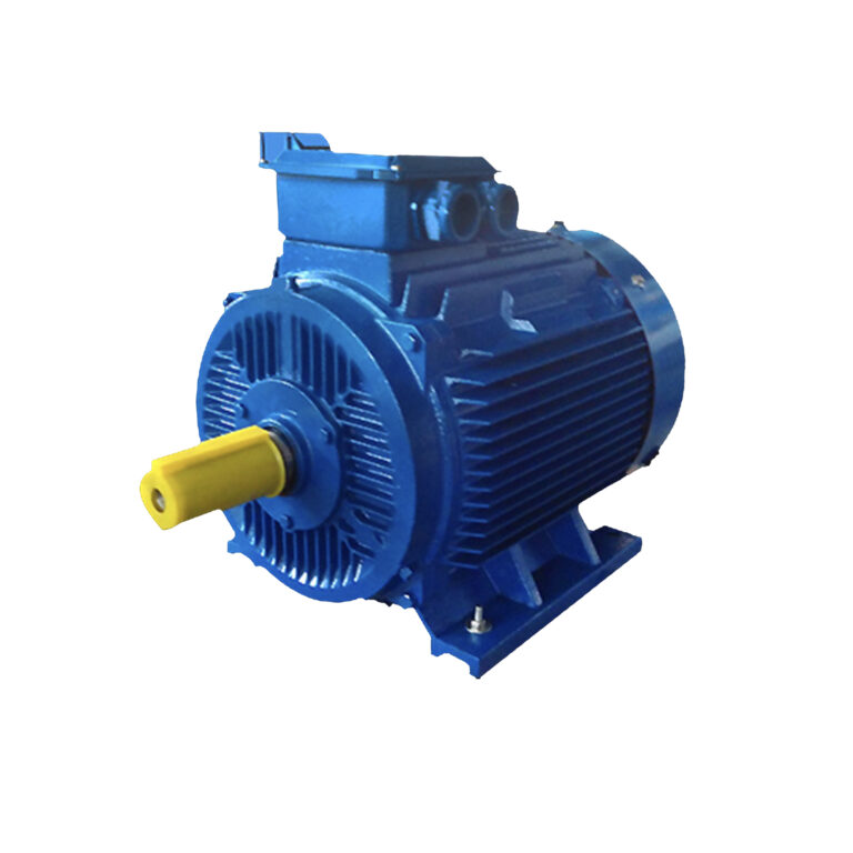
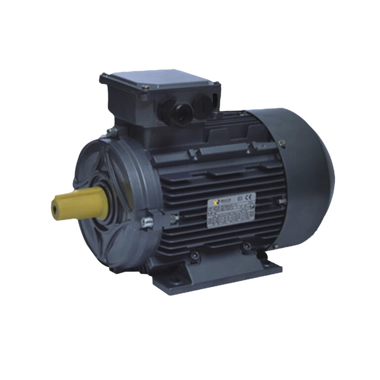
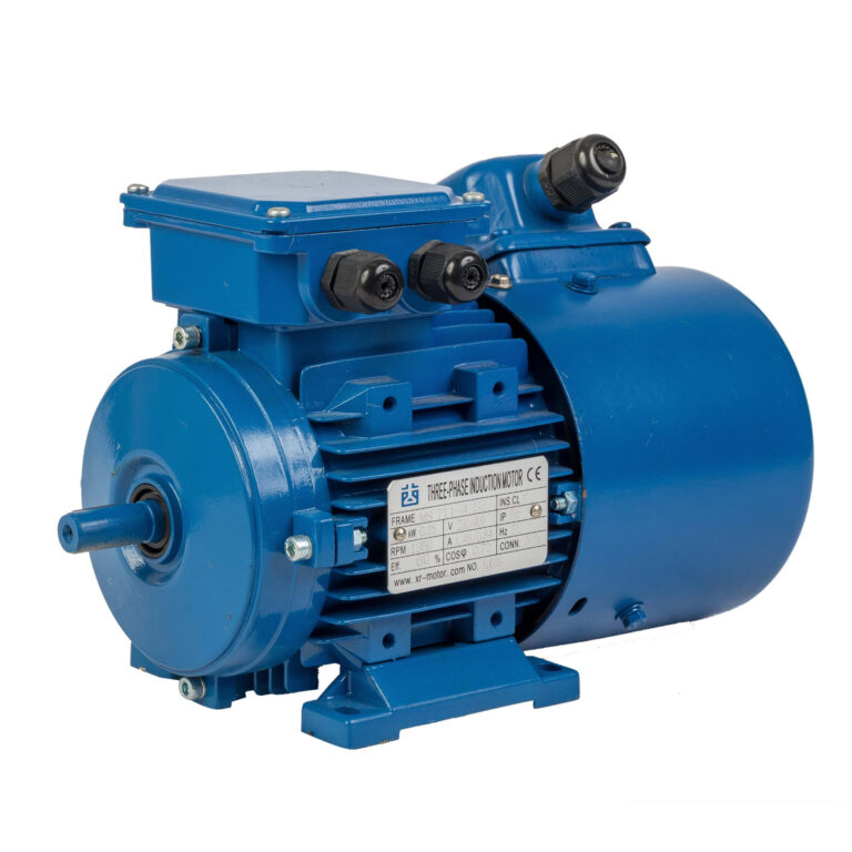
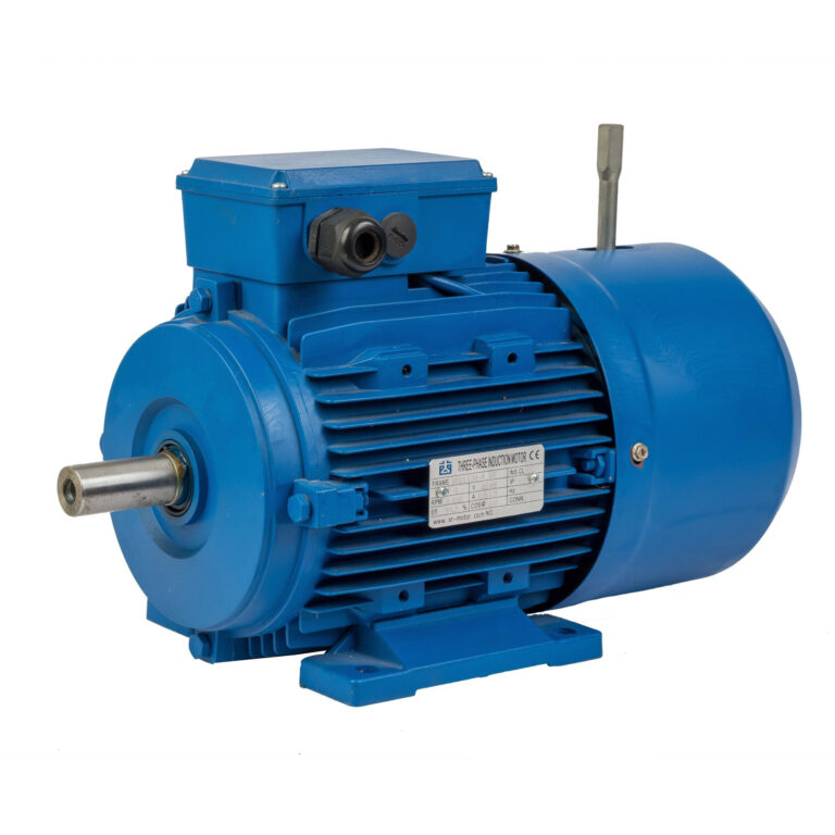
B5 Flange Motor vs B3 Foot Mounted Motor
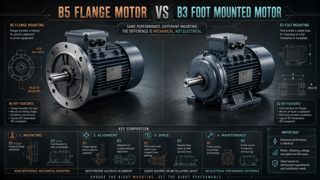
A B5 flange motor and a B3 motor mainly differ in their mounting structure. When power, pole number, voltage, and efficiency class are the same, their speed, efficiency, and output capability are generally similar.
The correct choice depends on the machine interface, available space, transmission method, and mechanical support. DAYOU MOTOR supplies both flange and foot mounted motor configurations for pumps, fans, gearboxes, conveyors, and OEM machinery.
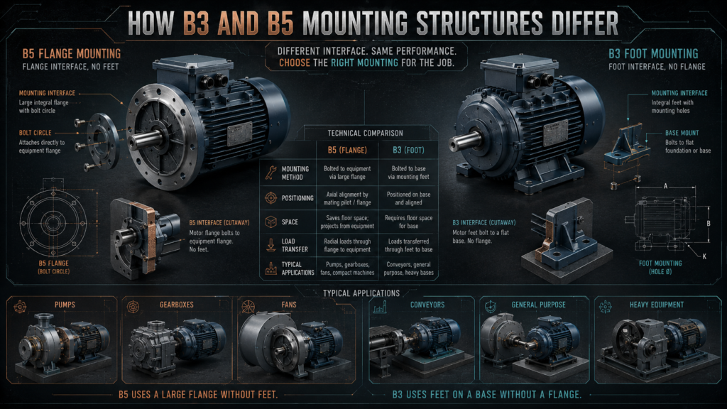
How B3 and B5 mounting structures differ
The defining feature of a B5 flange motor is its large end-shield flange. The motor is secured directly to a pump, gearbox, fan housing, or machine face, while the flange register helps locate the motor concentrically.
A B3 design has mounting feet but no flange. It is bolted to a baseplate, frame, or foundation, making it suitable for coupling, belt, and chain transmission.
Comparison | B5 mounting | B3 mounting |
Mounting method | Large flange without feet | Feet fixed to a base |
Positioning | Located by the flange register | Aligned through the feet and base |
Space requirement | Compact without a separate motor base | Requires a mounting surface |
Load transfer | Through the flange into the machine housing | Through the feet into the frame |
Alignment | Convenient for direct connection | Requires careful shaft alignment |
Maintenance | May need to be withdrawn from the machine | Usually easier to lift separately |
Typical applications | Pumps, gearboxes, fans, and mixers | Conveyors, crushers, fans, and general machinery |
Belt drive | Requires a mechanical load check | More convenient for belt adjustment |
The B3 vs B5 motor decision is therefore mechanical rather than electrical. A flange does not increase motor power or efficiency, while mounting feet do not reduce performance.
Choose B5 for direct machine connection
Choose a B5 flange motor when the motor must connect directly to a pump, gearbox, fan housing, or equipment end plate. Its compact structure removes the need for a separate motor base and usually provides repeatable positioning after maintenance.
A flange connection can help maintain concentricity, but it does not correct inaccurate machining. The flange register, equipment bore, shaft, coupling, and fastening surface must still be manufactured within suitable tolerances.
A buyer looking for a flange mounted motor supplier in China for European pump OEMs should provide the required IEC frame, flange dimensions, shaft details, mounting direction, and equipment drawing before sample production.
Choose B3 for flexible installation
A B3 design is normally more practical when the machine already has a common baseplate or when the motor drives equipment through a flexible coupling, belt, or chain.
The feet allow the installer to adjust position, coupling alignment, and belt center distance. This flexibility is useful during maintenance because the motor can often be removed without dismantling the driven machine.
A B3 motor for Southeast Asian conveyor systems should be selected according to starting torque, gearbox ratio, belt load, ambient temperature, dust, humidity, and starts per hour, not only by rated power.
For belt-driven equipment, the shaft and bearings must withstand the radial load created by belt tension. Correct pulley alignment and belt tension are also necessary to prevent bearing damage.
Mechanical loads require separate checking
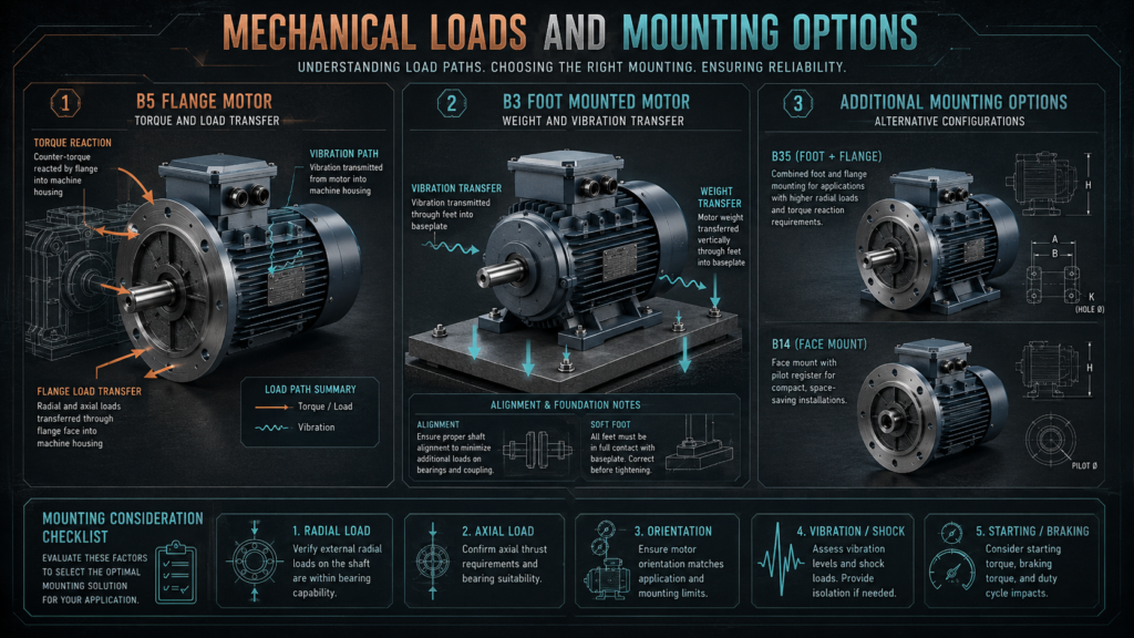
A B5 flange motor transfers its weight, torque reaction, and vibration through the flange into the driven equipment. The equipment housing and flange connection must therefore provide enough stiffness and support.
A B3 unit transfers these forces through its feet into the base or frame. Soft foot, an uneven mounting surface, or incorrect shimming can distort the frame and increase vibration.
Neither mounting style should be expected to carry unlimited external loads. Buyers should provide the supplier with:
- Coupling or pulley type
- Pulley diameter and belt tension
- Radial and axial shaft loads
- Driven-equipment weight and inertia
- Horizontal or vertical orientation
- Expected vibration and shock
- Starting and braking conditions
These details allow the manufacturer to check the shaft, bearings, flange, and housing.
B35 and B14 provide additional options
When equipment needs both a large flange and mounting feet, the B35 arrangement is often suitable. The flange supports direct alignment, while the feet help carry motor weight and mechanical loads.
A B14 motor uses a smaller flange, normally with threaded mounting holes. It is common in compact machinery and small gearboxes where a large B5 flange would occupy too much space.
When reviewing IEC motor mounting types for Middle East machinery projects, buyers should also consider high ambient temperature, dust, corrosion, terminal-box position, and whether the motor will operate horizontally or vertically.
A B14 motor for compact equipment in South America must still match the local voltage, frequency, flange register, thread size, and shaft dimensions.
Vertical installation needs additional confirmation
A horizontally designated flange motor should not automatically be installed with its shaft pointing upward or downward. Vertical mounting may change bearing loading, drainage, lubrication, cooling, and protection against falling water or debris.
The actual vertical mounting designation and permitted shaft direction should be confirmed with the manufacturer. Drain holes, grease points, terminal-box orientation, shaft seals, and any protective cover may also need adjustment.
Replacement motors require dimensional verification
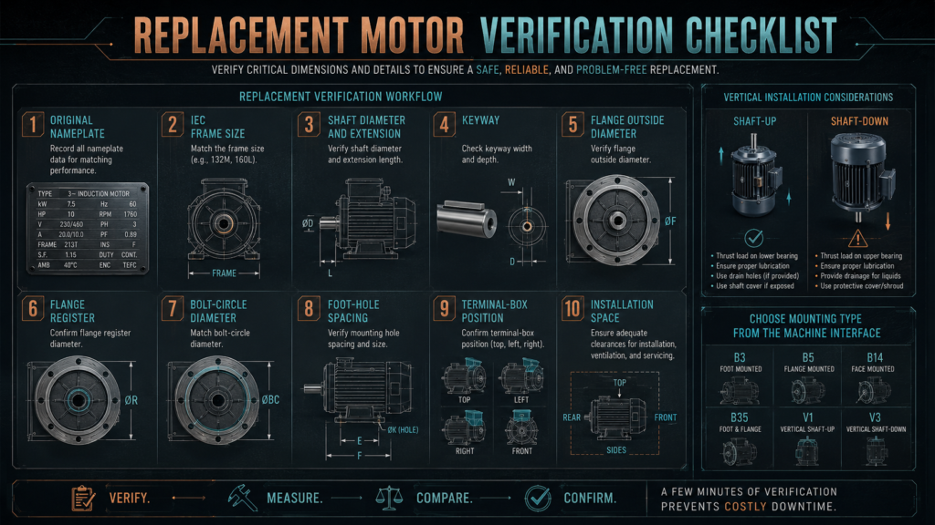
Replacing a B3 unit with a B5 flange motor, or changing from B5 to B3, normally requires changes to the machine structure. Matching power and speed does not make the two configurations mechanically interchangeable.
Before replacement, check:
- IEC frame size
- Rated power and actual speed
- Shaft diameter and extension
- Key and keyway dimensions
- Flange outside diameter
- Flange register diameter
- Bolt-circle diameter and hole size
- Foot-hole spacing
- Terminal-box and cable-entry position
- Available installation and removal space
A buyer searching for a foot mounted motor replacement for UK industrial equipment should provide the original nameplate and a dimensional drawing. Older motors may not match the dimensions of a current standard series even when their power ratings are identical.
Frequently asked questions
Does a B5 motor perform better than a B3 motor?
No. If their electrical designs and ratings are equivalent, the two motors normally provide similar speed, torque, efficiency, and output. Their main difference is how they connect to the machine.
Can a B5 motor be used with a belt drive?
It may be possible, but the flange support, shaft, bearings, pulley size, and radial load must be checked. A B3 arrangement is usually more convenient for adjusting belt tension and center distance.
Can a B35 motor be used without its feet?
Some motors have removable feet and may support this conversion, but it should not be assumed. The manufacturer must confirm the permitted configuration and mounting orientation.
Is a B5 motor suitable for vertical installation?
Only when the motor design and specified mounting position allow it. Bearing arrangement, drainage, cooling, shaft direction, and protective features should be confirmed before installation.
Choose the mounting type from the machine interface
The right choice between a B5 flange motor and a B3 design depends on the support structure and load path. B5 is compact and well suited to direct equipment connection, while B3 offers greater installation flexibility and easier adjustment on a common base.
DAYOU MOTOR supplies B3, B5, B14, and B35 motors with different powers, voltages, efficiency classes, protection levels, and customized mechanical interfaces. Providing the equipment drawing and operating conditions before ordering is the most reliable way to avoid installation problems.