


- Home
- Product
- GOST standard motor
- IEC standard motor
 MC Series single phase capacitor start asynchronous motor
- MY MYT series single phase capacitor running asynchronous motor
- ML Series single phase dual-capacitor asynchronous motor
- ME2 series three phase high efficiency aluminum housing motor(IE2)
- ME3 series three phase high efficiency aluminum housing motor(IE3)
- MS series three-phase aluminum housing motor (IE1)
- Y2 series three phase cast iron motor (IE1)
- YE2 series three phase high efficiency cast iron motor (IE2)
- YE3 series three phase high efficiency cast iron motor (IE3)
- Special application motor
- Rolling door motor
- Industry application
- News
- About us
- Contact us
- Certifications
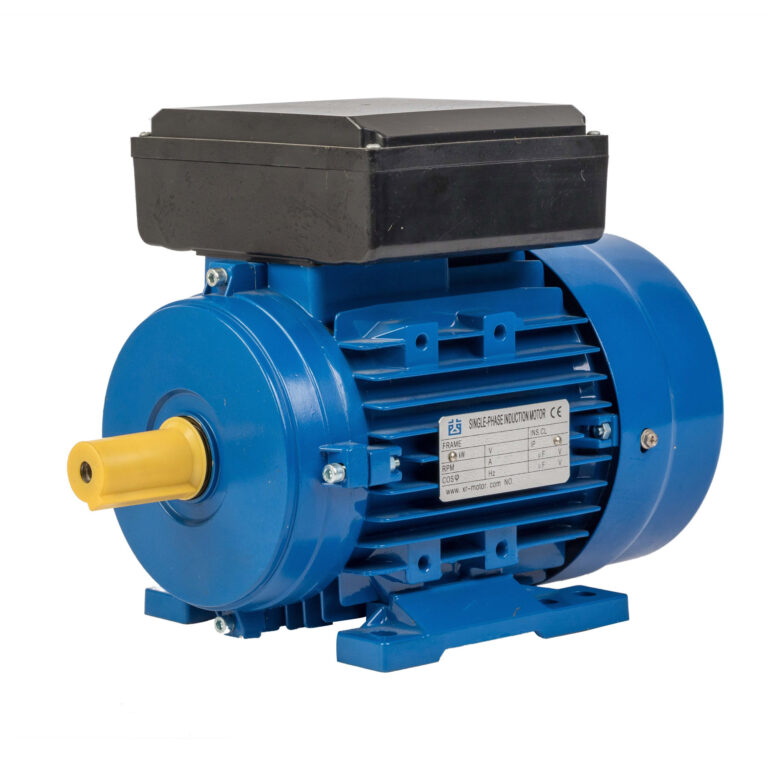
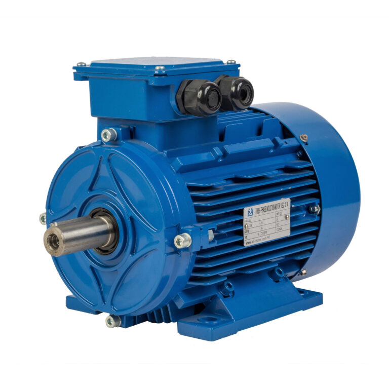
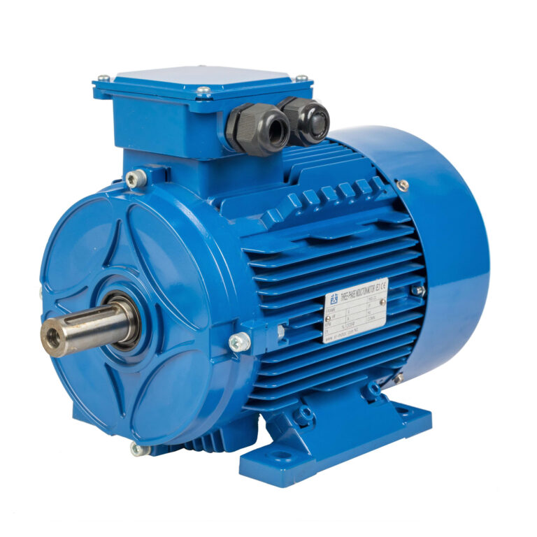
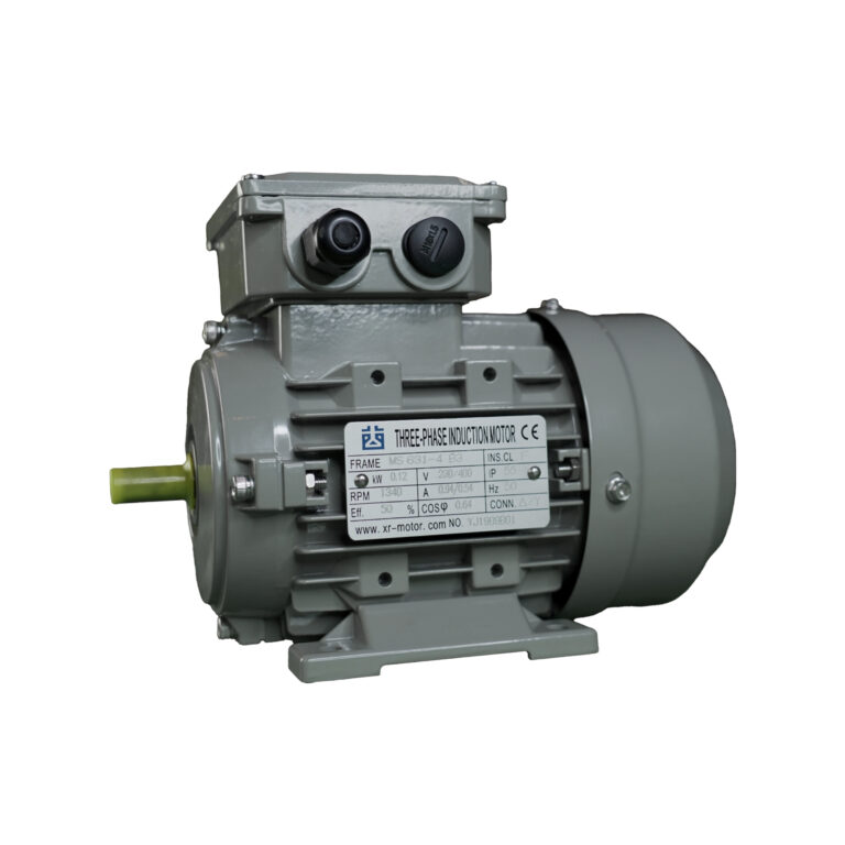
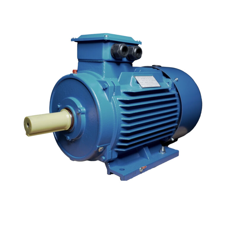
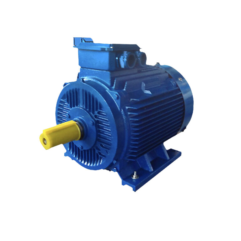
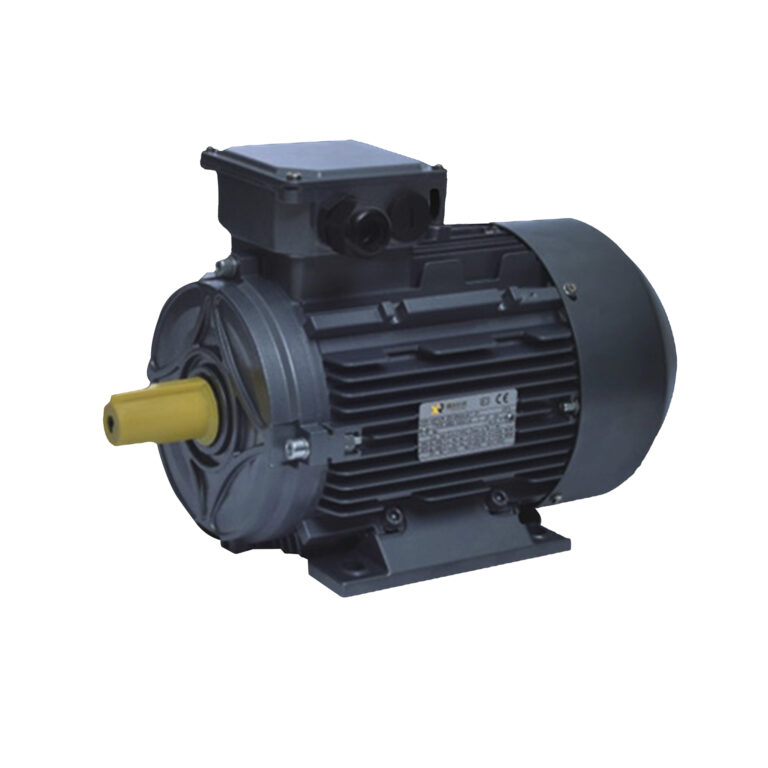
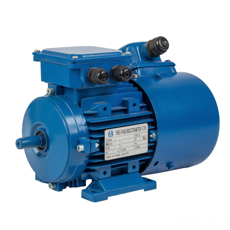
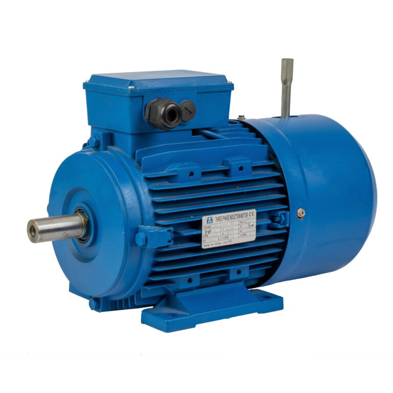
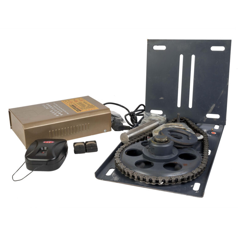
B3, B5, B14 and B35 Motor Mounting Types: How to Choose the Right One
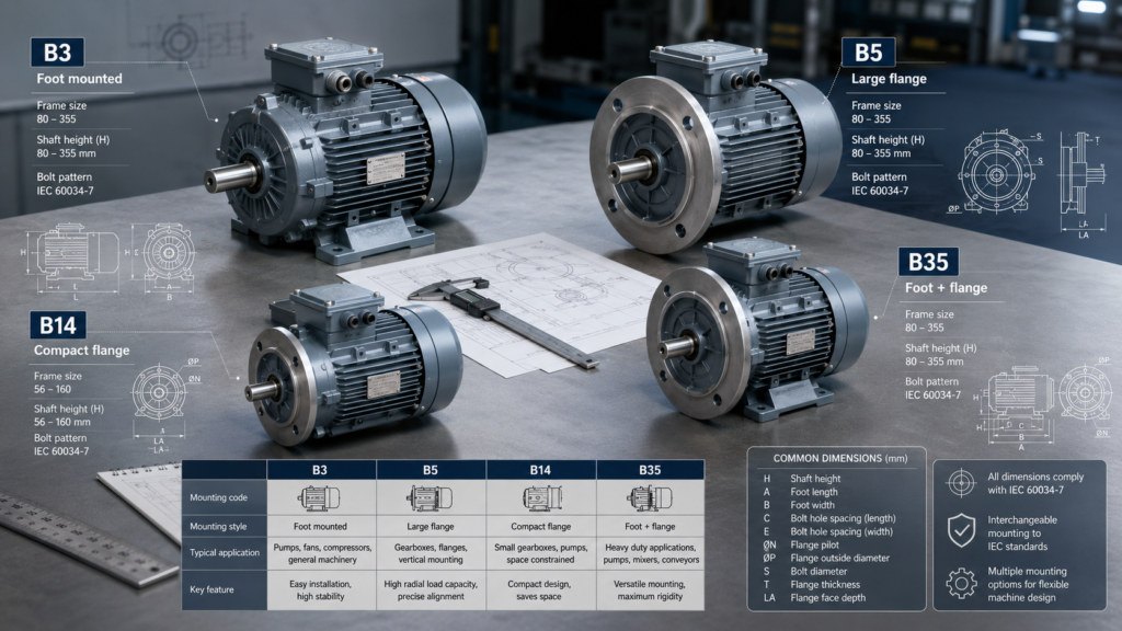
Choosing between a B3 motor and a B5 motor rarely feels difficult until the motor arrives at the assembly line and the bolt holes, shaft height, or flange dimensions do not match the equipment. In practical machine design, these motor mounting types affect more than installation convenience; they influence alignment, load support, maintenance access, available space, and the long-term reliability of the complete drive system.
IEC Mounting Codes Describe More Than a Simple Installation Position
IEC 60034-7 classifies rotating electrical machines by construction, mounting arrangement, and terminal-box position through the IM Code system. IEC 60034-7:2020 provides both alphanumeric and numeric classification systems, which is why buyers should confirm the complete mounting designation and dimensional drawing instead of relying only on a familiar shorthand name.
In my experience, confusion around motor mounting types usually begins when a purchasing team assumes that two motors with the same kW rating and frame size are directly interchangeable. Their electrical ratings may match, but a different flange, foot arrangement, shaft extension, or terminal-box orientation can make one unit impossible to install.
B3 Is a Practical Choice When the Machine Has Its Own Base
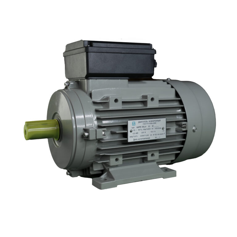
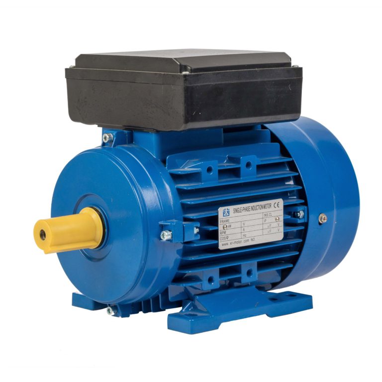
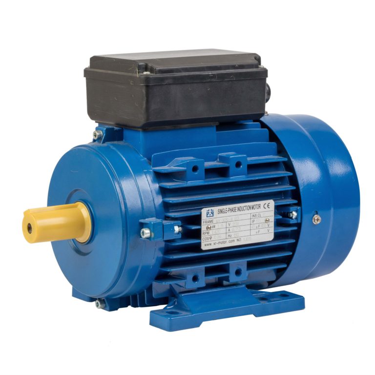
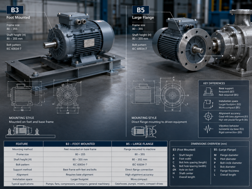
A B3 motor uses feet for horizontal mounting and does not rely on a flange for support, which makes it a common option for fans, pumps, belt-driven machinery, chain drives, and conveyors installed on steel frames or concrete foundations. Because the motor sits on a base or platform, technicians can usually access it easily for alignment, inspection, and replacement.
For many general industrial applications, a B3 motor offers a straightforward and economical installation method. Its flexibility is especially useful where the machine designer can adjust the motor position to set belt tension or align a coupling accurately.
B5 Works Well When the Motor Connects Directly to Equipment
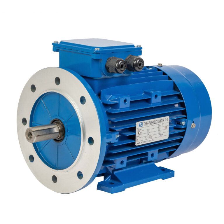
A B5 motor uses a large flange rather than mounting feet, allowing the motor to bolt directly to a gearbox, pump housing, machine wall, or other driven equipment. This arrangement is often preferred when floor space is limited or when the motor must be supported by the driven machine itself.
A properly selected B5 motor can help maintain good concentricity between the motor and the connected equipment, although the flange diameter, locating spigot, bolt pattern, and shaft dimensions must be checked carefully. In my view, this detail deserves special attention because a flange that looks similar from a distance can still have a different pitch circle diameter or locating diameter.
B14 Fits Compact Machinery Where Space Is Limited
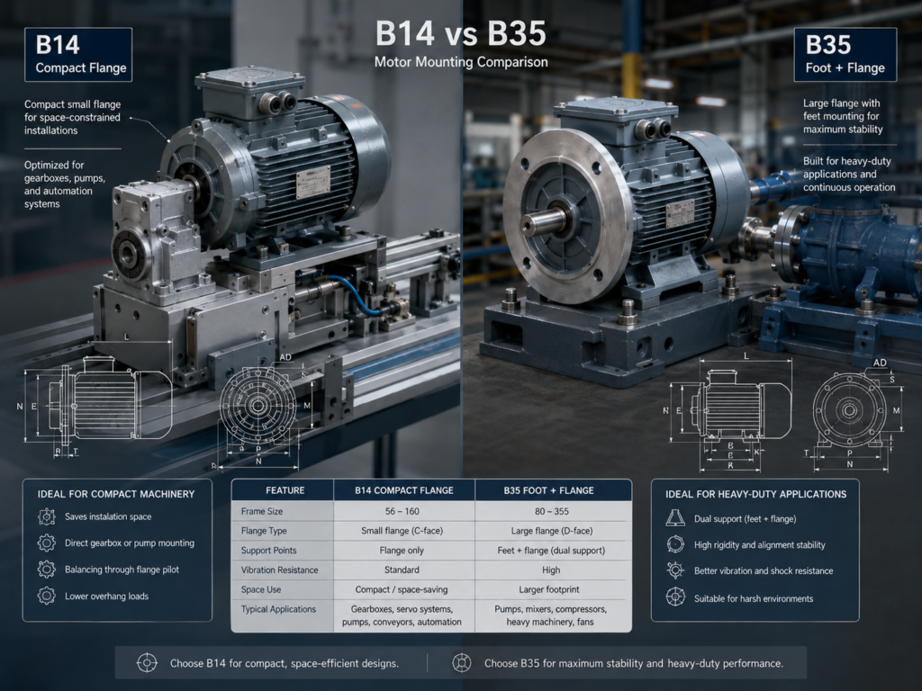
B14 mounting uses a smaller flange and is widely used on compact gearboxes, small automation equipment, and light-duty machinery where a large flange would interfere with nearby components. The mounting holes are commonly threaded, but the exact arrangement should always be verified against the drawing because dimensions vary by frame size and equipment design.
A customer once asked for a B5 replacement for a compact worm gearbox, but the surrounding machine guards left no room for the larger flange. The correct solution was a B14 configuration, which fitted the gearbox properly without requiring changes to the equipment enclosure.
B35 Gives the Design Both Feet and a Large Flange
B35 combines mounting feet with a large flange, making it useful when the design benefits from both base support and flange alignment. Heavy gearmotor applications, vibration-prone equipment, and larger driven assemblies may use this arrangement when the equipment structure can support both mounting points.
During a conveyor project I reviewed, the team had specified a B3 motor because the equipment included a base frame, yet the gearbox interface had been designed for a flange-mounted connection. Changing the drawing to accept a B5 motor solved the alignment issue without adding an unnecessary support structure. That case reminded me that the right choice among motor mounting types should follow the actual support points of the machine, not simply the most common motor configuration in stock.
Procurement Specifications Should Freeze the Mechanical Interface
A buyer working with a B3 motor supplier in China should confirm frame size, foot-hole spacing, shaft height, shaft extension, keyway, terminal-box orientation, paint requirements, and nameplate details before production begins. For a B5 motor manufacturer for Middle East projects, flange dimensions, environmental protection, heat conditions, and installation drawings deserve the same level of attention.
Regional purchasing requirements can also differ. A B14 flange motor supplier in Europe may need to support compact machine interfaces and detailed dimensional documentation, while a B35 foot and flange motor manufacturer in South America may be asked to provide robust mounting solutions for mining, water treatment, or heavy processing equipment. Buyers who source motor mounting types for Southeast Asian OEMs should likewise verify local voltage requirements, common gearbox interfaces, and expected spare-parts availability.
DAYOU MOTOR helps customers confirm these details through technical drawings and application-based selection, which is often the most effective way to prevent an installation mismatch before shipment.
A Few Checks Can Prevent an Expensive Replacement Error
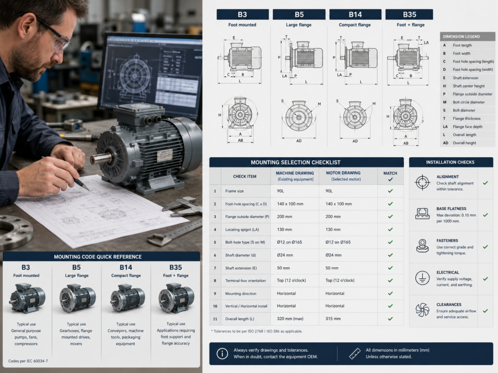
Before approving a B3 motor or B5 motor, compare the motor drawing with the machine drawing rather than checking the nameplate alone. The flange outside diameter, pitch circle, locating spigot, bolt-hole type, shaft dimensions, foot spacing, and mounting direction should all be reviewed.
It is also worth confirming whether a vertical installation is required, because vertical motors can have different bearing and weather-protection requirements from horizontal designs. DAYOU MOTOR recommends documenting the complete mechanical interface during the RFQ stage, since clear requirements make later replacement, inspection, and warranty support much easier.
The Best Mounting Choice Is the One That Matches the Machine
A suitable B3 motor provides practical base-mounted flexibility, while a correctly specified B5 motor can create a compact and accurately aligned direct connection. B14 and B35 configurations serve equally important roles when machine space, flange size, vibration, or support requirements call for a different arrangement.
DAYOU MOTOR believes that selecting the right motor mounting types should be treated as an engineering decision, because the correct configuration helps the motor fit properly, run reliably, and remain serviceable throughout the equipment’s working life.