

In daily life, many people may wonder why electric motors emit a deep running sound and convert electrical energy into mechanical power to drive the world. The answer lies in the rotor and stator. The rotor and stator are crucial components of an electric motor. The stator is the outermost cylinder, with numerous windings wound inside. These windings are connected to an external AC power source. The entire cylinder is fixed to the frame, hence the name “stator.” Inside the stator are either cylinders wound with numerous wires or cage-like cylinders, connected to the motor’s output shaft and rotating at the same speed; these are called the rotors. There is no direct connection or contact between the stator and rotor, but when the stator windings are connected to AC power, the rotor immediately begins to rotate and output power. These two components are the “backbone” of every electric motor; together, they generate a magnetic force that drives the normal operation of various devices. Furthermore, an AC motor is an electromechanical converter that can be used as either a motor or a generator. When used as a motor, it can generate a rotating electromagnetic field using three-phase current. When used as a generator, it can produce three-phase current. Three-phase current is an alternating current with three phases. Dayou Motor boasts 20 years of experience focusing on high-efficiency motor manufacturing, consistently leading the trend of green manufacturing. We deeply understand that the design, material selection, and precision manufacturing of the rotor and stator play a decisive role in creating a motor that simultaneously possesses stable reliability, superior energy efficiency, and long-lasting performance. From the thickness of the silicon steel sheets to the arrangement of the copper windings, every detail profoundly affects the motor’s operating status, energy consumption level, and lifespan in harsh industrial environments.
Often, people overlook the two core components, the stator and rotor, focusing instead on the motor’s external characteristics or price. However, the quality of the rotor and stator directly determines the total cost of the motor over its entire lifespan. In this blog post, we will break down the fundamentals of the rotor and stator, deeply analyze their structure, explain their working principles in easy-to-understand language, and showcase the innovative technologies Dayou Motor employs in building high-efficiency motors.
1. The Stator: The Stationary Core of Electric Motors
Speaking of the stator, it is the stationary core of the electric motor. In the operation of an electric motor, the stator, the outer casing, remains stationary while generating a rotating magnetic field that drives the rotor. If the stator cannot generate a strong and stable rotating magnetic field, the rotor will remain stationary, and the motor cannot function. We can think of the stator as the stage for the rotor’s “performance,” providing the magnetic field foundation for its rotation. Each stator is meticulously designed to ensure both uniform magnetic field generation and efficient operation. Any unevenness or weak points in the magnetic field can lead to decreased motor performance, increased energy consumption, and even wear on components.
The stator is not a single metal part; it consists of three key components working together: the stator core, the stator windings, and the housing. These three parts play crucial roles in the overall function of the stator, and the quality of each directly affects the performance and durability of the entire motor. At Dayou Motor, we strive for meticulous control over every detail of these three components, using high-quality materials and precision manufacturing techniques. Through these efforts, I believe our stators meet the highest industry standards.
1.1 Stator Core: The Main Body of the Magnetic Circuit
The first part of the stator is the stator core, which is the main body of the stator’s magnetic circuit and provides a path for the flow of the magnetic field inside the motor. Generally, the stator core is made of ultra-thin silicon steel sheets laminated together because silicon steel has high magnetic permeability, allowing it to easily conduct magnetic flux. For the stator core, eddy current losses are the main cause of energy waste and heat generation in the motor, so we can reduce these losses through a laminated structure. As we know, lamination can effectively cut off eddy current paths, minimizing energy loss and allowing the motor to operate at a low temperature and high efficiency. Dayou Motors uses high-quality silicon steel for its stator cores, and we customize and differentiate designs according to different motor series to ensure reduced energy loss while striving for optimal magnetic performance.
1.2 Stator Windings: The Source of the Magnetic Field
The second part of the stator is the stator winding, which is a copper-aluminum coil wound around the teeth of the stator core and is the source of the motor’s magnetic field. When alternating current is applied to these windings, a rotating magnetic field is generated, which moves around the interior of the stator at a constant speed. The design of the stator windings is crucial. The number of turns, their arrangement, the copper wire diameter, and the slot fill factor all affect the motor’s voltage, current, torque output, and efficiency. Dayou Motors employs a combination of fully automatic and semi-automatic winding and coiling equipment to ensure uniform and precise winding arrangement, minimizing performance instability caused by human error. We can also customize stator windings to meet different needs and applications.
1.3 Stator Housing: Fixation and Heat Dissipation
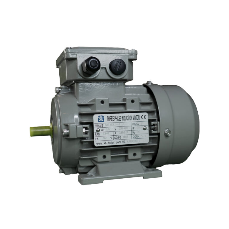
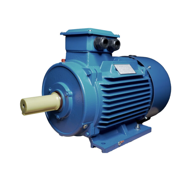
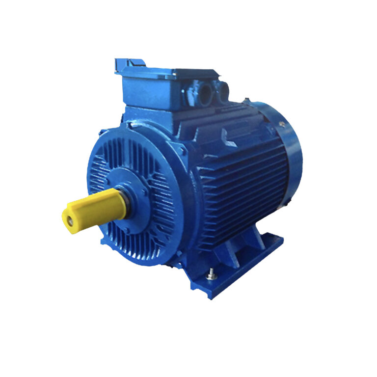
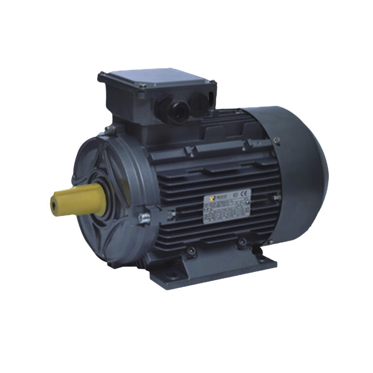
The third part of the stator is the housing. The housing is the external structure that secures the stator core and windings and is also a critical heat dissipation component. During operation, the motor may generate heat due to energy loss. If this heat cannot be effectively dissipated, it can damage the windings, reduce motor efficiency, and shorten its lifespan. Industrial motor housings are typically designed with cooling fins, which improve heat dissipation by increasing the surface area. Dayou Motors offers both aluminum alloy and cast iron housings for different customers. Aluminum alloy housings are lightweight and compact, making them suitable for equipment with limited weight and space constraints. Cast iron housings are robust, durable, and have excellent heat resistance, making them suitable for heavy-duty industrial applications.
1.4 Working Principle of the Stator: Generating a Rotating Magnetic Field
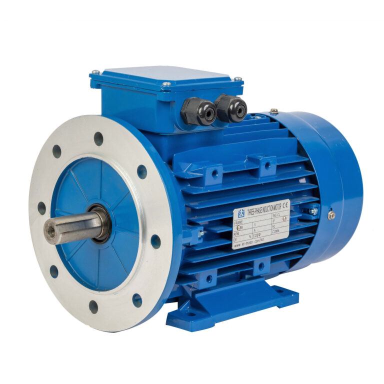
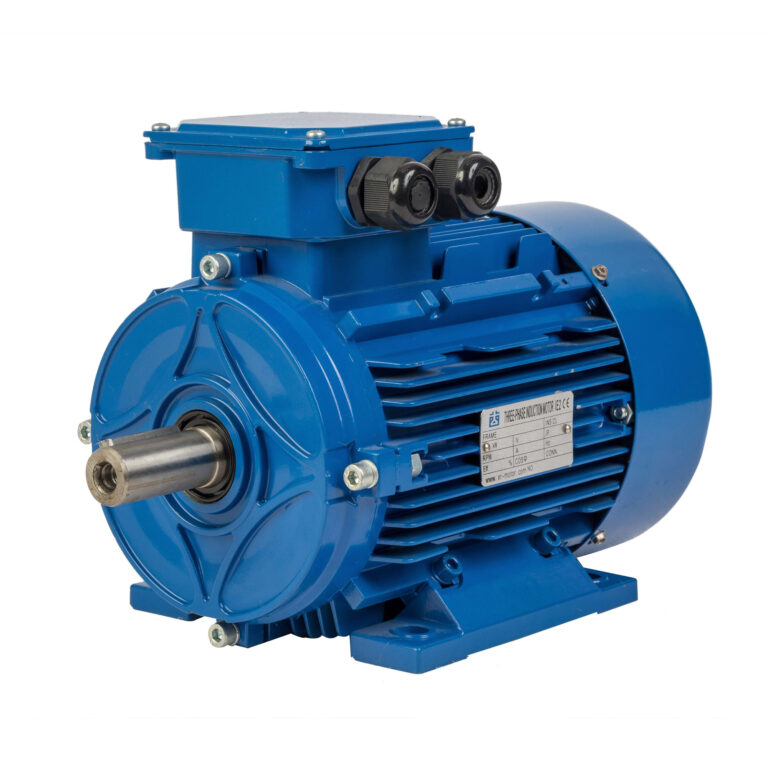
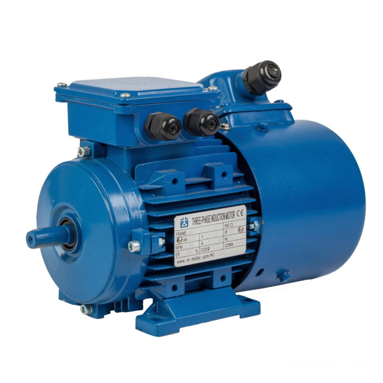
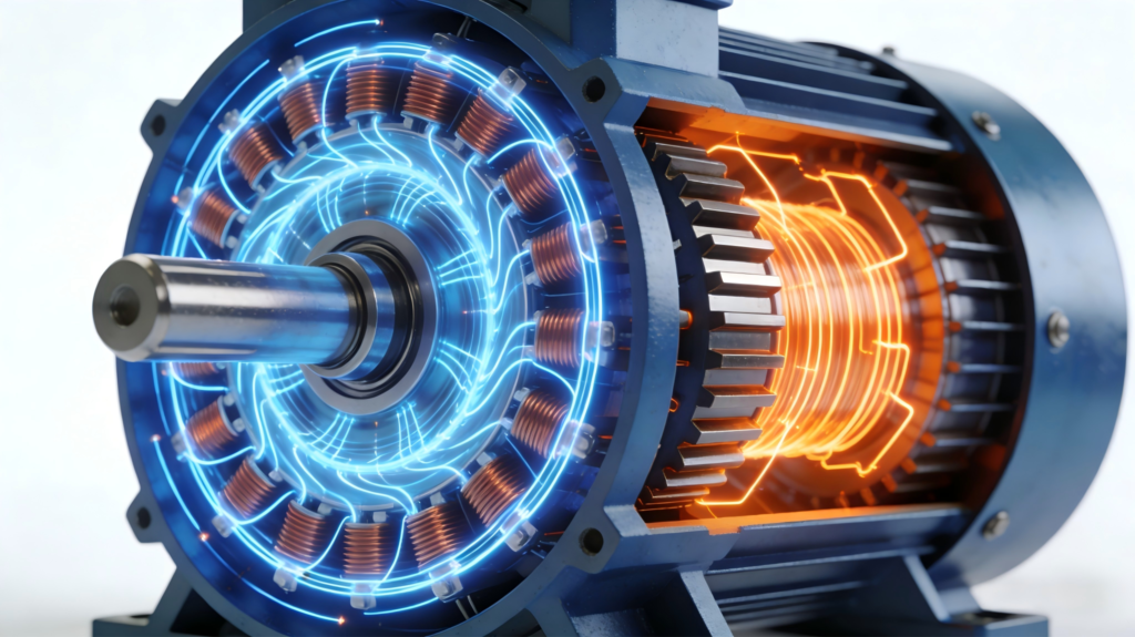
The core function of the stator is to generate a rotating magnetic field, which is essentially the core principle of electromagnetic induction. In the most common industrial applications, three-phase AC motors have three windings evenly distributed on the inner circumference of the stator core. When three-phase AC current is applied to these windings, each winding generates a magnetic field, the intensity of which increases or decreases over time. The three superimposed magnetic fields combine to form a unified rotating magnetic field, thus driving the rotor to rotate and converting electrical energy into mechanical motion.
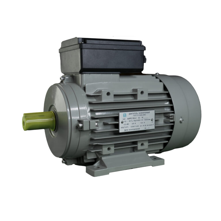
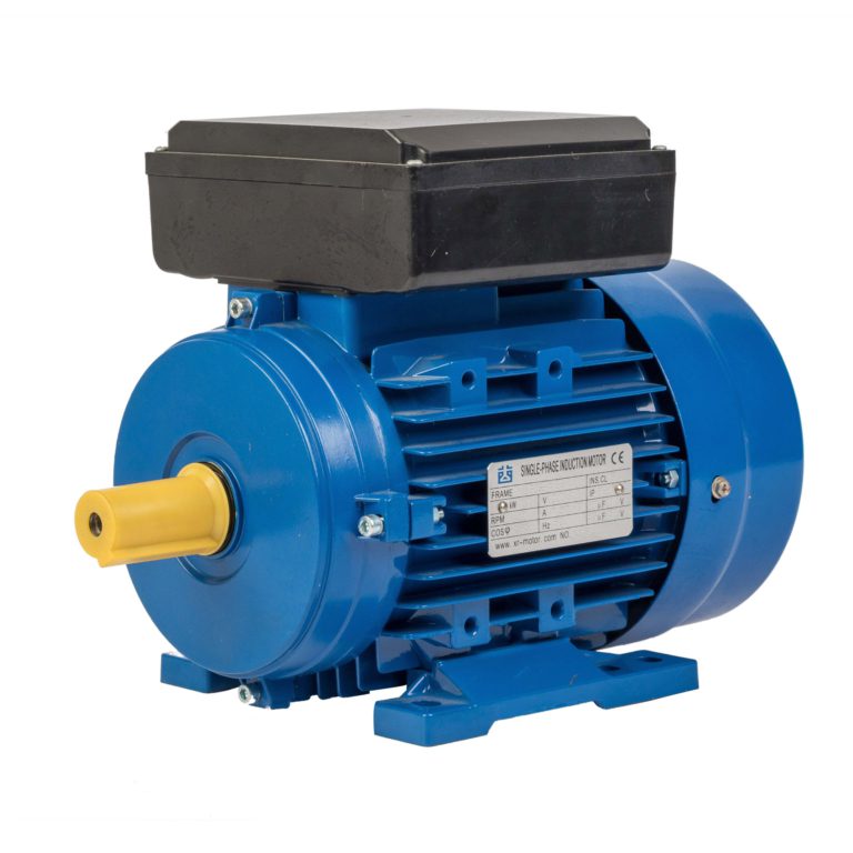
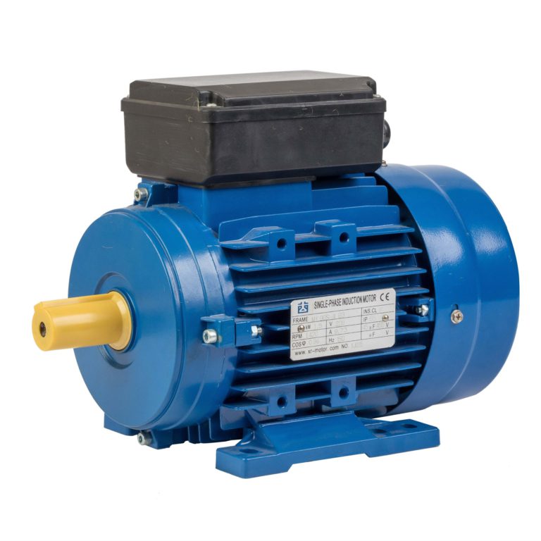
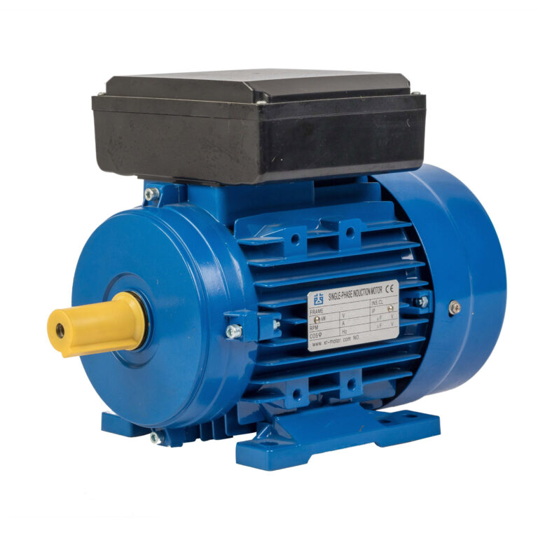
Even in single-phase motors used in small devices like fans, the stator can generate a rotating magnetic field, but with the aid of capacitors. Single-phase AC current itself can only produce a pulsating magnetic field. The starting capacitor can change the current phase in one winding, creating a slight imbalance between the magnetic fields, thereby starting the rotor. Dayou Motor’s single-phase series motors utilize precision stator windings and high-quality capacitor design to ensure reliable starting and smooth operation.
2. The Rotor: The Rotating Component That Converts Magnetic Force to Mechanical Motion
The stator and rotor are interdependent. The rotor, located inside the stator and mounted on the motor shaft, is a rotating component responsible for converting the stator’s rotating magnetic field into actual mechanical motion. Simultaneously, the rotor is the core component for “doing work,” transmitting mechanical power to the motor. Without the rotor, the stator’s magnetic field cannot function, nor can it supply magnetic force to the drive equipment. Like the stator, the rotor’s design, material selection, and precision manufacturing directly affect the motor’s operating efficiency, torque output, and overall reliability.
Similar to the stator, the rotor consists of three main working parts: the rotor core, the rotor conductors, and the motor shaft. Each of these parts has a specific function, and their quality and precision are crucial to the rotor’s performance. Dayou Motor employs advanced manufacturing equipment and rigorous quality control processes to ensure that every rotor meets high production standards.
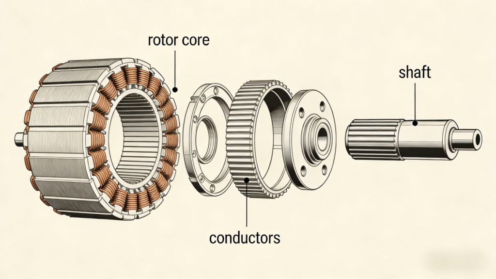
2.1 Rotor Core: Reducing Eddy Current Losses
The first part of the rotor is the rotor core. Similar to the stator core, the rotor core is made of ultra-thin silicon steel sheets laminated together to reduce eddy current losses. The rotor core is cylindrical with slots on its outer surface for placing the rotor conductors. The rotor core is tightly mounted on the motor shaft and rotates together with the shaft in the stator magnetic field. For high-speed, high-efficiency motors, the rotor core must have sufficient rigidity to withstand the centrifugal force during rotation. Dayou Motors’ rotor cores are machined using high-speed precision stamping equipment to ensure perfect roundness and slot alignment.
2.2 Rotor Conductors: Interacting with the Stator Magnetic Field
The second part of the rotor is the rotor conductors, which are the parts of the rotor that interact with the stator magnetic field. Unlike the stator coils, the rotor conductors are not directly connected to the power source. Instead, they are driven to generate current within the conductors through electromagnetic induction in the stator’s rotating magnetic field. This rotor current generates a secondary magnetic field opposite to the stator magnetic field. The interaction of these two magnetic fields produces a Lorentz force, which propels the rotor to rotate in the direction of the stator’s rotating magnetic field. Dayou Motors is working diligently to optimize the shape, size, and material of its conductors to maximize the current and resistance that its rotor conductors can withstand, striving to output maximum torque.
2.3 Motor Shaft: Supporting and Transmitting Power
The third part of the rotor is the motor shaft, a solid metal rod that passes through the center of the rotor core. Its function is to support and transmit the power source. It secures the rotor to the stator via bearings and transmits the rotor’s rotational torque to the motor, allowing the motor to operate under load. We carefully select the shaft material and diameter based on the power output and application requirements of different motors. Dayou Motors uses high-quality steel for its shafts, which undergo precision grinding to ensure perfect roundness and coaxiality, thereby reducing bearing vibration and wear. The rotor’s motion is based on the principle of electromagnetic induction. The rotating magnetic field of the stator cuts the rotor conductors, inducing a current within the conductors. This current drives a rotor magnetic field, and the interaction between the two magnetic fields causes the rotor to rotate. However, it’s important to note that the rotor’s speed is always lower than the stator’s synchronous speed; this slight speed difference is called slip, and it is crucial for maintaining the magnetic field cutting the rotor conductors and generating the induced current. Slip determines the torque of a motor. Dayou Motor optimizes and designs rotors according to different application scenarios to strive for the ideal slip ratio.
3. Types of Rotors in AC Asynchronous Motors
In AC asynchronous motors most widely used in industrial and commercial applications, rotors are mainly divided into two categories: squirrel-cage rotors and wound-rotor rotors. Both designs have their unique advantages, disadvantages, and ideal application scenarios, allowing us to choose based on the specific needs of different applications. Dayou Motor focuses on manufacturing squirrel-cage rotors because of their simpler structure, greater reliability and durability, and perfect alignment with our initial goal of providing high-performance and cost-effective motors to global customers.
3.1 Squirrel-Cage Rotors: Simple, Reliable and Cost-Effective
The squirrel-cage rotor, named for its unique shape, consists of a series of parallel metal bars and annular end rings connecting the bars at both ends. This simple design makes it a popular choice for industrial and commercial motors, robust and durable while being easy to mass-produce, suitable for a wide range of applications. Most of Dayou Motor’s motor series use squirrel-cage rotors because they offer stable performance and require minimal maintenance.
The conductors of squirrel-cage rotors are typically made of aluminum or copper. Aluminum is used in small and medium-sized motors due to its lower cost and ease of die casting; copper is used in high-efficiency and high-power motors due to its lower resistance and higher energy efficiency. Most motors from Dayou Motors use high-purity aluminum die-cast squirrel-cage rotors, ensuring uniform conductor thickness and tight contact with the end rings. The advantages of squirrel-cage rotors are significant: simple and reliable structure, no easily damaged parts, suitable for harsh industrial environments; virtually maintenance-free, requiring only occasional bearing lubrication; high cost-effectiveness, with mass production reducing costs; smooth operation, low vibration and noise; and wide applicability to various scenarios. Its limitations mainly include limited starting torque, large direct starting inrush current, and the inability to adjust speed itself. However, these problems can be solved using soft starters, frequency converters, and other equipment. Dayou Motors further improves the performance of squirrel-cage rotors through optimized design to meet the needs of different scenarios.
3.2 Wound-Rotor Rotors: Suitable for High Starting Torque Applications
Wound-rotor designs are more complex than squirrel-cage rotor designs. They are suitable for applications requiring high starting torque or where speed adjustment can be achieved without a frequency converter. It features insulated copper wire windings similar to those on the stator, connected to three slip rings on the motor shaft. External resistance can be connected to the rotor circuit via brushes, allowing for resistance adjustment and control of the motor’s starting torque and speed.
The advantages of wound-rotor motors are high starting torque, heavy-load starting capability, low inrush current, and speed regulation without a frequency converter. They are also suitable for special applications such as cranes and winches. However, their limitations are also significant: wound-rotor motors have a more complex structure and higher cost; they require regular brush replacement, resulting in higher maintenance costs; their efficiency is lower than squirrel-cage rotors, and their durability is poorer.
Dayou Motors focuses on the specific needs of its customers, collaborating with partners to provide relevant solutions. Dayou Motors is also actively seeking suitable alternatives to achieve equivalent results and deliver a perfect customer experience.