

If you’ve ever worked with motors, especially the three-phase asynchronous motors commonly used in industrial production, you’ve undoubtedly heard of “slip.” Many people are curious about this term for the first time and may have various misunderstandings: What is slip? Is it inaccurate motor rotation? Or is it a loss? Is it a design flaw? Some people mistakenly believe that the smaller the slip, the better, ideally zero, for a motor to be considered perfect.
Actually, these ideas are inaccurate. Slip is not a defect of the motor; on the contrary, it’s the core key to the normal operation of an asynchronous motor and its ability to drive a load. Without slip, an asynchronous motor cannot rotate. In this article, we’ll discuss the core theories and principles of slip, explaining all the relevant knowledge and experience clearly. We’ll also combine this with our design experience with Dayou Motors to enhance our understanding of the theory and its practical application.
1.0 First, understand: Why is an asynchronous motor called “asynchronous”?
1.1 What is an asynchronous motor?
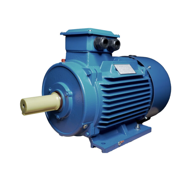
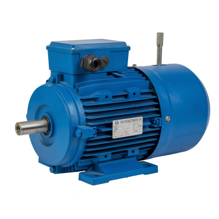
Before understanding slip, we should first understand the meaning of asynchronous. Asynchronous motors are the most widely used and prevalent type of motor worldwide. They are used in over 90% of factory fans, pumps, machine tools, and everyday appliances like air conditioners and washing machines. Their core advantages are reliability, simple structure, and ease of maintenance.
1.2 Core working principle of asynchronous motor
The core working principle of an asynchronous motor is “electromagnetic induction.” It mainly consists of a stator and a rotor, and its working logic involves four steps.
1.2.1 The stator generates a rotating magnetic field
First, the stator is energized with alternating current, generating a rotating magnetic field. This magnetic field rotates at a fixed speed, known as “synchronous rotational speed,” determined by the power supply frequency and the number of poles.
1.2.2 The rotating magnetic field cuts the rotor conductors
Second, the rotating magnetic field continuously cuts the rotor conductors to generate electromagnetic torque. However, this cutting requires relative motion, and there must be a difference in speed between the magnetic field and the rotor.
1.2.3 Energy conversion process
Third, the process of inducing current in the conductors after cutting and converting electrical energy into rotor energy is completed.
1.2.4 The rotor generates torque and rotates
Finally, the rotor experiences a force after inducing current in the magnetic field, generating electromagnetic torque to drive the rotation of the rotor and the load. We must understand that the synchronous speed of the rotating magnetic field is always faster than the actual speed of the rotor; the two are not synchronized, which is the origin of the term “asynchronous motor.” This asynchrony is not a defect, but a necessary condition for the motor’s operation. Without relative motion, there is no magnetic field cutting, and therefore no power.
1.3 Definition of slip and slip ratio
The difference in speed between the magnetic field and the rotor is called “slip”; the ratio of slip to synchronous speed is called “slip ratio.” Simply put, the formula is: Slip ratio = (Synchronous speed – Actual rotor speed) ÷ Synchronous speed. Essentially, it represents the degree to which the rotor “lags” behind the magnetic field, measuring the magnitude of relative motion.
1.4 Analogy to understand slip
For example, imagine two people running. The person in front runs at a constant speed, while the person behind can never catch up. The difference in distance between them is the “slip,” and the ratio of this distance difference to the speed of the person in front is the “slip ratio.” If their speeds were the same, the person in front wouldn’t provide any thrust, and the person behind would stop. This is entirely consistent with the logic of an asynchronous motor.
2.0 Core Theory: What is the essence of slip ratio?
The core of slip ratio is not the calculation of the formula; its core is the bridge. In short, slip is the bridge for energy conversion in an asynchronous motor, connecting electrical and mechanical energy. Simply put, slip is an indicator of the intensity of electromagnetic induction. The larger the slip of the motor, the faster the magnetic field cuts the rotor, the larger the induced current in the rotor, and the greater the output torque of the motor; conversely, the smaller the slip, the less effective the motor.
3.0 Key Theory: Without slip, an asynchronous motor won’t turn!
3.1 Common misunderstanding of slip
This is the most easily misunderstood point: slip is not a fault, not an error; it is the “soul” of the asynchronous motor, the fundamental reason why the motor rotates and drives the load. Many people think that the smaller the slip, the better, even wanting it to be 0, which is putting the cart before the horse. When the slip is 0, the motor will immediately stop and cannot work at all.
3.2 Analogy to understand the necessity of slip
This concept can also be compared to running. Only when the person in front is faster than the person behind can they provide a push for the person behind; if the speeds are the same, there is no push, and the person behind will stop. The same principle applies to asynchronous motors. The rotor can rotate; its core function is the induced current and torque generated by the magnetic field cutting through the rotor. The prerequisite for this cutting is relative motion, the magnitude of which is determined by the slip rate.
3.3 Practical example of slip function
For a practical example, the motor in a fan is an asynchronous motor. Under normal operation, its slip rate is 1% to 3%, resulting in stable relative motion. If the fan blades are forcibly held down, the slip rate becomes 100%, causing a sharp increase in current. The motor will attempt to drive the blades, but holding it down for an extended period could burn out the motor. This is the core function of slip rate. Without it, the motor has no power. Therefore, asynchronous motors must have slip rate during operation; it is a prerequisite for electromagnetic induction and the fundamental source of torque generation. This is not a defect, but a necessary condition for the normal operation of the motor.
4.0 The Theory of Synchronous Speed: Why is it Fixed? What is its Relationship with Slip Rate?
4.1 Definition and characteristics of synchronous speed
Synchronous speed is the rotational speed of the rotating magnetic field. It is constant and also the basis for slip rate calculation and the key to understanding slip rate changes. Its size is determined by only two factors, and is independent of load and temperature:
4.1.1 Power supply frequency (f)
50Hz (changing 50 times per second) in China. The higher the frequency, the faster the magnetic field rotates, and the higher the synchronous speed.
4.1.2 Number of poles
Specifies the number of pole pairs in the sub-winding. 2 poles = 1 pair, 4 poles = 2 pairs. The more poles, the lower the synchronous speed. This will be clearly indicated on the motor nameplate.
4.2 Synchronous speed formula and common examples
Synchronous speed formula (simple understanding): Synchronous speed = (60 × power supply frequency) ÷ number of pole pairs. “60” converts the frequency per second to speed per minute. The core logic is still that “frequency and number of poles determine the speed.” Common Examples (China 50Hz Power Supply):
– 2-pole motor: Synchronous speed 3000 rpm, normal full-load slip 1%~3%, used in high-speed equipment;
– 4-pole motor: Synchronous speed 1500 rpm, normal full-load slip 3%~5%, the most commonly used motor in industrial production;
– 6-pole motor: Synchronous speed 1000 rpm, normal full-load slip 3%~5%, used in medium- and low-speed equipment.
4.3 Relationship between synchronous speed and slip
Core Connection: Synchronous speed is fixed, slip changes dynamically. The core of this change is the rotor speed, which is determined by the load. For example, a 4-pole motor has a constant synchronous speed of 1500 rpm. Under no-load conditions, the rotor speed is close to 1500 rpm (extremely small slip), under full load it is close to 1440 rpm (slip around 4%), and under overload conditions it is below 1440 rpm (slip > 5%).
5.0 Slip Rate Variation Pattern: Directly Related to Load, Automatically Adjustable
5.1 Basic rule of slip rate variation
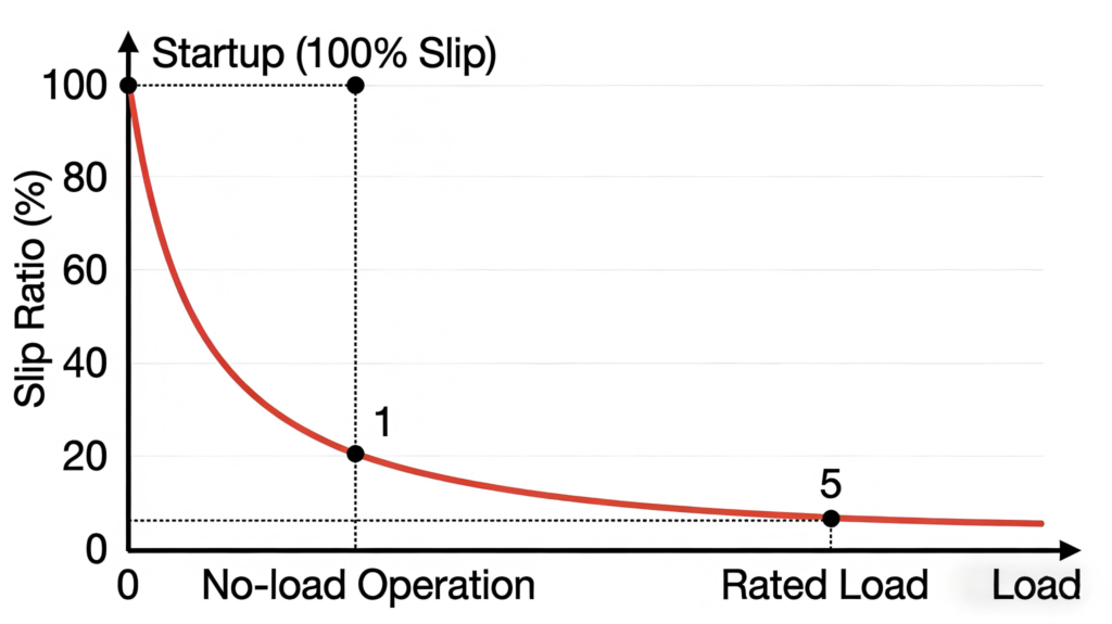
Slip rate is not a fixed value; its core influencing factor is actually the load, and it can automatically adjust. The lighter the load, the smaller the slip rate; the heavier the load, the larger the slip rate. Adjustment does not require manual operation, which is a core advantage of asynchronous motors, underpinned by the theoretical logic of “electromagnetic torque adaptive load.” Slip rate variations can be categorized into four common operating conditions, which we will analyze and understand using theory and simple scenarios:
5.1.1 Instant Start-up: Slip Rate is 100%
When the rotor speed is 0, slip rate = (synchronous speed – 0) ÷ synchronous speed = 1, which is the maximum slip rate. At this time, relative motion is at its maximum, the starting current is 5-8 times the rated current, and the maximum starting torque is generated to overcome the rotor’s inertia. Factories use “star-delta starting” when starting large motors to reduce the starting current and protect the equipment; this is based on the starting theory of slip rate.
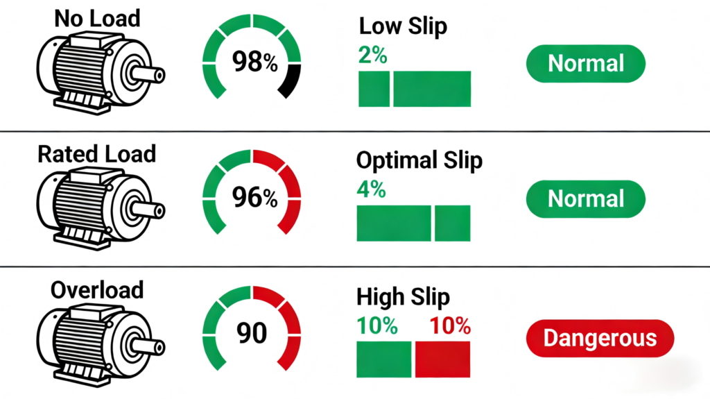
5.1.2 No-load operation: The slip rate is 0.3%~1%
With no load, the rotor only needs to overcome its own friction and air resistance. The required torque is relatively small, and the speed is close to synchronous speed, resulting in a very small slip rate. Therefore, the no-load current is also small, and heat generation is minimal. When inspecting a motor, starting it under no-load and observing the speed, sound, and temperature allows for assessment of the motor’s basic condition. This is a practical application of slip rate theory.
5.1.3 Rated load: The slip rate is 1%~5%
When the motor is operating under rated load, the rotor speed is stable, and the slip rate is within the optimal range. Electromagnetic induction is moderate, efficiency is highest, and temperature rise is reasonable. For example, the Dayou YE3 series high-efficiency asynchronous motor (IE3 class), 4-pole, 50Hz, has a rated slip rate stable at around 4% and an efficiency of over 90%, suitable for long-term continuous industrial operation. It is designed based on the optimal working theory of slip rate.
5.1.4 Overload Operation: Slip > 5%
When the load exceeds the rated value, the rotor will be dragged, causing a decrease in speed and an increase in slip. This leads to a surge in induced current, increased motor losses, and severe overheating. Prolonged overload can potentially burn out the windings. If you notice a decrease in motor speed, overheating of the casing, and excessive current, it is highly likely due to overload. In this case, check the load or mechanical jamming to troubleshoot the problem promptly.
6.0 The Core Role of Slip: Throughout Motor Design, Use, and Maintenance
6.1 Overview of slip’s core role
The role of slip is crucial throughout the entire lifecycle of a motor. Each role is theoretically supported and closely related to practical operation. Four core roles can be summarized:
6.1.1 The Sole Prerequisite for Torque Generation
Core Logic Chain: Slip → Relative Motion → Magnetic Field Cutting Rotor → Induced Current → Electromagnetic Torque → Motor Rotation. Slip is the starting point of this logic chain. Without slip, there is no torque, and the motor cannot operate. For example, a washing machine motor has a 100% slip at startup, generating starting torque to drive the inner drum. During operation, the slip is 1%~3%, ensuring stable operation.
6.1.2 Automatic Adaptation to Load Changes
Asynchronous motors require no external controller and can automatically adjust slip according to load: As the load increases, the rotor speed decreases, the slip increases, and the torque increases until equilibrium is reached; as the load decreases, the rotor speed increases, the slip decreases, and the torque decreases, until equilibrium is reached again. For example, in a workshop fan, when doors and windows are open (increased load), the slip automatically increases to ensure stable airflow; when doors and windows are closed (lightened load), the slip decreases, saving energy.
6.1.3 Determining Motor Starting Performance
At startup, slip = 100%. Starting torque and starting current are closely related to the slip design. Designers optimize the rotor structure to ensure smooth starting characteristics. Dayou Motors also customizes its products for different scenarios to ensure starting performance is adapted to the operating conditions.
6.1.4 “Health Check Indicators” for Judging Motor Condition
We can quickly determine the motor’s condition based on the pattern of slip changes:
When the full-load slip is 1%~5%, the motor can operate normally.
When the no-load slip is <1%, the motor can operate normally, but prolonged no-load operation may waste energy.
When the full-load slip is >5%, the motor is overloaded and requires troubleshooting.
When the slip suddenly increases sharply, the motor may be malfunctioning.
When the slip approaches 100%, the moment of startup may cause the motor to seize up and the windings to burn out.
7.0 Relationship between Slip and Torque: The “Core Business Card” of Motor Performance
7.1 Slip-torque curve (s-T curve) overview
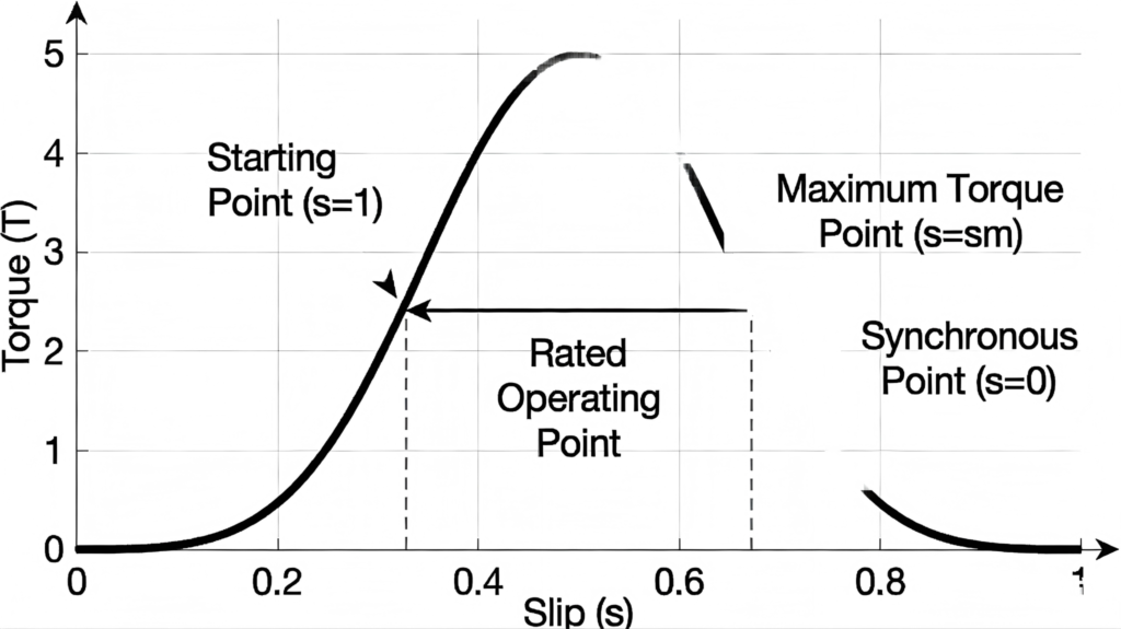
Every asynchronous motor has a “slip-torque curve” (s-T curve), which is the core of motor performance, determining starting performance, maximum torque, and stability range. The theoretical logic of key nodes is as follows:
7.1.1 Starting Point (s=1): Corresponding to Starting Torque
At the moment of starting, the slip is 100%. The starting torque determines whether the motor can start: For light load starting (fans, water pumps), the starting torque is 1.0~1.5 times the rated torque; for heavy load starting (crushers), it needs to be 2.0~3.0 times or more to ensure overcoming inertia.
7.1.2 Maximum Torque Point (s=sm, Critical Slip): Corresponding to Maximum Torque
The highest point of the curve is the maximum torque, which is the maximum force the motor can output. This determines its overload capacity. If the load exceeds the maximum torque, the motor will stall. Dayou Motors optimizes the curve to strive to improve the maximum torque, enhance overload capacity, and ensure stable operation even under load fluctuations.
7.1.3 Rated Operating Point (s = Rated Slip): Corresponds to Rated Torque
A slip rate of 1%~5% corresponds to the rated torque. This is the point where the motor has the highest efficiency and reasonable temperature rise, and is also the optimal operating point. When selecting a motor, we should choose one with a rated torque greater than or equal to the load torque to ensure normal operation.
7.1.4 Synchronization Point (s = 0): Corresponds to Torque = 0
The rotor and magnetic field rotate at the same speed. Without torque, the motor will stop rotating, which again proves that a motor with a slip rate of 0 cannot operate. Designers will design the slip curve according to different scenarios. Fans and water pumps require smooth curves, while crushers require steep curves. Each product from Dayou Motor can be adapted to the corresponding scenario to achieve the effect of optimizing slip rate.
8.0 Practical Case: Quickly Determining Motor Status Using Theory
8.1 Case overview
Assume a factory has a 4-pole, 50Hz asynchronous motor with a nameplate indicating a rated speed of 1440 rpm, no-load speed of 1490 rpm, and overload speed of 1400 rpm. We can use theory to determine its status:
8.1.1 Synchronous Speed Calculation
4-pole motor (2 pairs of poles), synchronous speed 1500 rpm (fixed);
8.1.2 Rated Status Judgment
1440 rpm close to 1500 rpm, slip rate between 1% and 5%, normal;
8.1.3 No-Load Status Judgment
1490 rpm close to 1500 rpm, slip rate 0.3% to 1%, normal;
8.1.4 Overload Status Judgment
1400 rpm deviates significantly from 1500 rpm, slip rate > 5%, dangerous, requires shutdown and inspection.
8.2 Case conclusion
Therefore, as we can see, once we understand the theory of slip rate, we can quickly determine the motor’s status without complex calculations.